


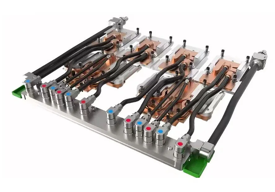
What Is Visible in This GPU Cooling Assembly?
The image shows multiple metallic cold-plate bodies connected by black flexible hoses to a front distribution block. Several connectors carry red or blue marks, and larger hoses run along the outer edges. This arrangement illustrates how a GPU cold plate assembly can package coolant distribution, thermal interfaces, and service connections into a removable server tray.
The photograph does not establish a specific server model, coolant, material grade, internal channel design, connector standard, or rated performance. Those items must come from the released BOM, drawings, OEM specifications, and qualification records. This distinction matters when sourcing parts for a Rubin-class or other high-density AI server.
How the Coolant Path Works
A typical server liquid cooling circuit receives conditioned coolant from a rack manifold through a supply connection. A tray distribution block or hose network divides that flow among the cold plates. Heat travels from each processor package, through the thermal interface and cold-plate base, and into the moving coolant. Return hoses collect the warmer fluid and route it back through the rack loop to a CDU or heat exchanger.
Whether the cold plates operate in parallel, series, or a mixed arrangement changes the pressure drop, temperature rise, and flow balance. Parallel branches can reduce the temperature rise between devices, but each branch must receive adequate flow. Series circuits simplify some routing while increasing downstream coolant temperature. The architecture should be verified with a hydraulic model and measured flow data.
Functions of the Main Components
| Component | Primary function | What to verify |
|---|---|---|
| GPU cold plate | Transfers device heat into coolant | Contact area, flatness, mounting pattern, thermal resistance, channels, proof and leak tests |
| Flexible hose | Routes coolant between fixed interfaces | Coolant compatibility, bend radius, pressure, permeation, abrasion, clamp and fitting retention |
| Distribution block | Splits or collects branch flow | Port layout, branch balance, pressure drop, internal deburring, cleaning and sealing |
| UQD quick disconnect | Supports controlled installation and service | Interface standard, flow coefficient, pressure rating, cycle life, residual fluid and valve behavior |
| Tray and brackets | Control location, support, and service alignment | Datums, stiffness, connector alignment, hose clearance, installation sequence and fasteners |
Why Tray-Level Liquid Cooling Is Used
Direct liquid cooling moves a large share of processor heat into a liquid loop instead of relying on server fans and room air. That can support higher heat density, reduce airflow pressure, and make rack thermal management more predictable. A tray-level assembly also gives the server manufacturer a controlled package for cold plates, hoses, fittings, and interfaces.
Serviceability is not automatic. Tight hose routing, inaccessible connectors, trapped liquid, poor labeling, or incompatible seals can increase maintenance risk. The mechanical layout should give technicians clear access, positive connector lock indication, protected bend radii, and an approved isolation and drain sequence.
Selection and Design Checklist
- Thermal input: define device heat loads, contact zones, allowable temperatures, thermal interface material, and cold-plate resistance targets.
- Hydraulic input: define coolant, total and branch flow, pressure drop budget, operating pressure, transients, and allowable temperature rise.
- Connections: control UQD standard, keying, supply/return identification, seal material, alignment, cycle life, and service state.
- Hose routing: check bend radius, torsion, abrasion, clamp spacing, tolerance stack, and clearance through the complete install path.
- Compatibility: review all wetted metals, coatings, elastomers, plastics, brazes, solders, and cleaning residues as one coolant system.
- Evidence: define dimensional inspection, cleanliness, leak rate, proof pressure, flow balance, pressure drop, and traceability records before sourcing.
Leak and Functional Validation
Validation should start with controlled requirements rather than an improvised shop test. A test specification needs the medium, pressure, ramp rate, stabilization period, temperature, acceptance limit, instrument accuracy, and disposition of failed parts. Pressure decay, bubble testing, tracer gas, and proof testing answer different questions; no single method replaces the rest of the qualification plan.
After leak testing, measure total and branch flow where the design requires it. Confirm pressure drop, look for trapped air, and verify that supply and return labels match the drawing. Drying, capping, bagging, and cleanliness controls are important because retained test liquid or particles can compromise a clean server loop. See our cold plate leak testing guide for method selection.
Frequently Asked Questions
Does every GPU cold plate need a supply and return connection?
Each active coolant path needs a way for coolant to enter and leave. Multiple cold plates may use individual pairs, a shared manifold, or another qualified circuit architecture.
What do red and blue marks on liquid cooling connectors mean?
They commonly identify supply and return or hot and cold sides, but the project drawing and service procedure must define the exact convention.
Can a UQD be disconnected while the server is operating?
Do not assume this from appearance. Confirm the connector rating, valve design, pressure state, residual-fluid behavior, platform controls, and OEM service procedure.
How should a GPU liquid cooling tray be leak tested?
Use a documented test medium, pressure, stabilization time, acceptance limit, instrumentation, and post-test drying process that match the drawing and coolant-system requirements.
What is needed to quote a custom tray assembly?
Provide controlled drawings, BOM, coolant, flow and pressure requirements, connector standard, hose routing, sealing materials, cleanliness criteria, test plan, quantity, and traceability needs.