


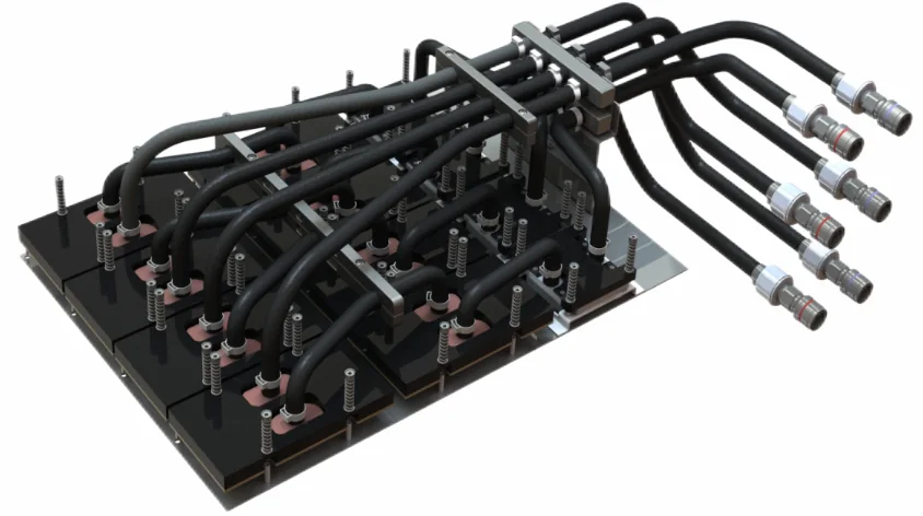
Visible Assembly Features
The image shows several dark rectangular modules arranged on a common base, many black hoses, spring-loaded mounting points, a metal hose-support structure, and multiple connectors at the right. These features illustrate a multi-device coolant assembly with repeated cold-plate positions and serviceable external connections.
From appearance alone, it is not possible to confirm the cold-plate internal geometry, coolant path, materials, seal design, connector standard, operating pressure, flow rate, heat removal, or exact GPU platform. Use the released drawing and BOM for every procurement or engineering decision.
How Parallel GPU Cooling Branches Work
In a parallel architecture, supply coolant divides among multiple GPU cold plate branches and then recombines on the return side. This can expose each device to a similar supply temperature. The challenge is hydraulic balance: coolant follows paths according to resistance, so small differences in channels, hose length, fittings, elevation, or assembly condition can change branch flow.
A branch with too little flow may operate above its intended thermal condition even when total tray flow appears correct. Design work should establish the pressure-drop curve of each branch, the available pump head, the expected coolant properties, and the full operating range. Qualification should measure the variables needed to show that every branch remains within its defined envelope.
What UQD Quick Disconnects Add
A universal quick disconnect can create a repeatable fluid interface between the cooling assembly and the server or rack loop. When correctly selected, it can reduce connection time, limit open-fluid handling, and simplify replacement. Selection must cover mating compatibility, flow restriction, pressure, temperature, valve behavior, residual spill, air inclusion, cycle life, keying, materials, and seal compatibility.
Installation and Acceptance Checklist
| Check | Acceptance focus |
|---|---|
| Cold-plate contact | Correct thermal interface material, contact area, surface condition, orientation, and controlled mounting sequence |
| Fasteners and springs | Specified hardware, torque or displacement, even loading, thread engagement, and witness controls |
| Hose routing | No kink, twist, abrasion, interference, excessive tension, or bend below the approved radius |
| Connector lock | Correct mates, clean interfaces, intact seals, full engagement, positive lock indication, and strain relief |
| Leak integrity | Documented medium, pressure, stabilization time, acceptance limit, instrumentation, and result |
| Flow performance | Total flow, branch balance where required, pressure drop, temperature, fluid state, and calibrated measurements |
| Cleanliness | Particle, oil, residue, moisture, capping, packaging, and handling criteria met |
Common Failure Risks
- Uneven mounting load: can reduce thermal contact or overstress the package and board.
- Hose torsion or kinking: can restrict flow and load fittings during installation.
- Damaged O-rings: can result from contamination, incompatible lubricant, incorrect material, or poor assembly.
- Partial connector engagement: may pass a visual glance while remaining mechanically or hydraulically unsafe.
- Unbalanced branches: can hide behind an acceptable total flow reading.
- Residual contamination: can obstruct microchannels, damage seals, or alter coolant chemistry.
RFQ and Qualification Inputs
A useful RFQ includes controlled 3D and 2D data, the assembly BOM, material and coating specifications, seal and connector requirements, coolant, operating and transient conditions, branch flow targets, pressure-drop limits, test methods, cleanliness, traceability, packaging, quantities, and change-control expectations.
For cold-plate manufacturing details, read CNC machined cold plates. For connection-system planning, see liquid cooling manifolds and UQD/NVQD.
Frequently Asked Questions
Why are GPU cold plates often connected in parallel?
Parallel branches can deliver coolant at a similar inlet temperature to multiple devices, but branch resistance and flow balance must be designed and measured.
What is the purpose of a UQD quick disconnect?
A qualified UQD can shorten installation or service time and limit fluid exposure, subject to its interface, valve, pressure, cycle-life, and residual-fluid specifications.
Can UQD fittings be disconnected under pressure?
Only if the exact connector and system procedure explicitly allow it. Appearance alone does not establish pressurized-disconnect or hot-swap capability.
How is branch flow checked?
Use a defined coolant or test fluid, controlled temperature and pressure, calibrated flow measurement, and acceptance limits for total and individual branch flow where required.
What should an assembly acceptance record contain?
It should identify the drawing revision, BOM, materials, seals, assembly controls, dimensional results, leak and pressure tests, flow results, cleanliness status, and traceability.