


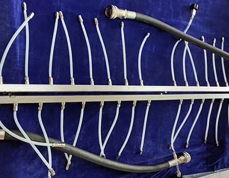
What Is a Rack Liquid Cooling Main Manifold?
A rack liquid cooling main manifold is the fluid-distribution backbone between the rack coolant source and multiple server or tray branches. The supply side accepts conditioned coolant from a CDU or secondary technology cooling loop and divides it among the rack positions. The return side collects warmer coolant from those positions and sends it back toward the heat exchanger or CDU.
Common names include rack manifold, liquid cooling distributor, supply header, return header, and distribution rail. The physical form varies: a design may use round tube, rectangular bar, welded pipework, machined blocks, or modular segments. The correct architecture depends on rack geometry, flow, pressure drop, service strategy, cleanliness, and production volume.
Supply and Return Flow Path
- The CDU or rack loop delivers conditioned coolant to the main supply connection.
- The supply manifold divides flow among numbered server branches.
- Branch hoses and quick disconnects route coolant into each server tray.
- Cold plates absorb processor heat and discharge warmer coolant.
- Return branches join the rack return manifold.
- The return main sends coolant to the CDU, where heat is transferred to the facility side or another rejection loop.
Flow does not divide evenly simply because branch ports look identical. Port geometry, branch length, hose routing, connector restriction, server pressure drop, elevation, and manifold pressure gradient all influence the result. Hydraulic modeling and commissioning measurements are needed when branch balance is critical.
Design and Sourcing Inputs
| Input | Why it matters | Evidence to request |
|---|---|---|
| Branch count and spacing | Matches rack positions and service reach | Rack layout, interface control drawing, branch map |
| Total and branch flow | Sets bore, port, valve, and balancing requirements | Design cases, hydraulic model, measured flow report |
| Pressure and pressure drop | Controls wall, joining, connector, and pump decisions | Operating, transient, proof, and loss requirements |
| Material and surface condition | Affects corrosion, joining, cleanliness, and coolant compatibility | Material certificate, process specification, wetted-material review |
| Ports and interfaces | Controls sealing, assembly, keying, and serviceability | Thread or connector standard, gauges, torque and seal instructions |
| Drain, vent, and sensors | Supports fill, air removal, monitoring, and maintenance | P&ID, service procedure, sensor and valve specification |
Is 316L Stainless Steel Required?
316L stainless steel is commonly considered for liquid cooling manifolds because it can offer corrosion resistance and weldability in suitable systems. It is not a universal requirement and should never be assigned from color or appearance. Aluminum, copper alloys, other stainless grades, polymers, and plated components may appear elsewhere in a loop.
Material selection must consider coolant chemistry, inhibitors, chloride exposure, galvanic couples, temperature, pressure, joining, passivation, internal surface condition, cleanliness, availability, and total cost. If 316L is required, state the exact specification, product form, condition, certification, welding procedure, filler, heat tint treatment, and acceptance criteria.
Manufacturing and Validation
Machined ports need controlled position, thread form, sealing faces, and burr removal. Welded assemblies need qualified procedures, stable fixturing, distortion control, internal purge where specified, and inspection of both leak integrity and flow obstruction. Long manifolds can accumulate dimensional error, making port location and straightness important for rack installation.
- Inspect critical datums, overall envelope, port position, threads, and sealing surfaces.
- Verify internal burr removal, chips, oil, weld residue, cleaning, flushing, drying, and capped packaging.
- Perform leak and proof-pressure tests under controlled parameters.
- Measure total pressure drop and branch flow where the design requires balance evidence.
- Record material heat, weld traceability, test equipment, operator, date, and unit serial or lot.
For manufacturing details, see liquid cooling manifold CNC machining. For system interfaces, review manifolds and UQD/NVQD connections.
Labeling and Service Access
Each branch should have an unambiguous rack position, supply or return designation, and flow direction. Labels support correct installation, alarm mapping, balancing records, and troubleshooting. Color can help, but durable text or coded identification should remain the controlling reference.
Leave enough space to operate connectors, valves, drains, and vents without bending neighboring hoses. Plan isolation boundaries and drip containment before the rack layout is frozen. A compact manifold that cannot be serviced safely can increase downtime and contamination risk.
Frequently Asked Questions
What is a rack liquid cooling main manifold?
It is a distribution assembly that divides supply coolant among multiple server branches and collects return coolant for the rack loop.
What is the difference between supply and return manifolds?
The supply manifold distributes conditioned coolant to branch circuits; the return manifold collects warmer coolant and routes it back toward the CDU or heat exchanger.
Is every rack manifold made from 316L stainless steel?
No. 316L is a common candidate, but the specified material must match coolant chemistry, pressure, joining, corrosion, cleanliness, cost, and system compatibility requirements.
Why should manifold branches be numbered?
Branch identification reduces connection errors and supports commissioning, flow balancing, alarm mapping, service records, and troubleshooting.
How is a rack manifold validated?
Validation can include dimensional inspection, weld review, cleanliness checks, leak and proof-pressure tests, pressure-drop measurement, branch flow balancing, and documented traceability.