


Verify the Platform Before Specifying the Tray
Rubin and NVL72 identify a product family and rack-scale architecture, not a universal mechanical interface. A tray, HPM-style liquid cooling module, hose, or connector should be selected only after the exact platform revision, OEM integration, controlled drawings, thermal limits, hydraulic envelope, and service procedure are known.
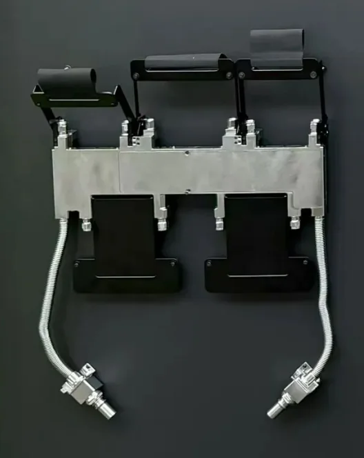
The reference image shows a metal support structure, several dark modules, two corrugated flexible hoses, and service connectors. It is useful for explaining packaging relationships. It does not verify the brand, model, internal flow path, materials, dimensions, flow, pressure, power, or compatibility.
How the Tray Structure Supports Cooling Hardware
The tray or carrier controls the position of cooling modules relative to processors, memory, power components, and server mechanics. Brackets support the assemblies and preserve alignment during installation. Flexible hoses absorb routing offsets and connect the tray loop to the rack or chassis interface. Connectors provide a controlled service boundary.
Every element participates in the tolerance stack. A mechanically stiff tray can still create connector side load if its datum scheme does not match the chassis. A flexible hose can still kink if the routing envelope ignores the minimum bend radius. Design reviews should consider the full insertion and removal path, not only the installed position.
Safe Maintenance Sequence
- Identify and authorize. Confirm the correct rack, server, tray, work instruction, and maintenance window.
- Shut down and isolate. Follow the platform procedure for workload shutdown, electrical isolation, coolant valve position, and alarms.
- Depressurize and control residual fluid. Verify pressure at the specified point and prepare approved containment.
- Disconnect deliberately. Support the hose, release the connector as instructed, cap exposed interfaces, and do not use force to correct misalignment.
- Inspect. Check sealing surfaces, O-rings, connector damage, contamination, hose abrasion, bracket condition, and evidence of leakage.
- Reconnect and refill. Align interfaces, confirm full lock, restore valves, remove air, and replenish approved coolant under the system procedure.
- Validate. Perform leak checks, verify flow and pressure behavior, clear alarms, and document the service action before return to operation.
Tray Liquid Cooling vs. Traditional Air Cooling
| Decision area | Tray liquid cooling | Traditional air cooling |
|---|---|---|
| Heat transport | Moves processor heat into a coolant loop close to the source | Moves heat through heat sinks, fans, server airflow, and room air |
| Density | Can support higher processor and rack heat density when the complete loop is designed for it | Limited by fan pressure, heat-sink volume, rack airflow, and facility HVAC capacity |
| Noise and fan energy | May reduce server fan demand, though pumps and residual air cooling remain | Often requires greater fan speed as heat density rises |
| Service complexity | Adds coolant isolation, connectors, seals, leak controls, and cleanliness procedures | Avoids server coolant connections but still needs airflow and dust management |
| Infrastructure | Requires manifolds, CDUs or equivalent loops, controls, treatment, and heat rejection | Requires sufficient room cooling, air distribution, and fan capacity |
Procurement Checklist
- Exact platform, configuration, revision, interface drawings, and approved-vendor requirements
- Cold-plate or module contact geometry, mounting pattern, flatness, and thermal requirements
- Coolant composition, operating temperature, flow, pressure drop, pressure, and transient conditions
- Connector standard, keying, alignment, valve behavior, residual-fluid limit, and cycle life
- Hose construction, wetted materials, bend radius, end fittings, routing, support, and abrasion protection
- Seal materials, approved lubricants, replacement interval, spare kits, shelf life, and storage
- Dimensional, cleanliness, leak, proof-pressure, flow, endurance, and traceability evidence
- Installation tools, technician training, service documentation, warranty, and failure-response ownership
Frequently Asked Questions
Is the pictured assembly confirmed as an NVIDIA Rubin NVL72 component?
No. The image is used to explain visible structural features. Exact origin and compatibility must be confirmed through part numbers, controlled drawings, and OEM documentation.
Can a liquid cooling tray be removed without draining the rack?
Only when the approved system design and service procedure support isolation and disconnection at the tray. Connector design, valve state, pressure, and residual-fluid control must be verified.
What should be checked before reconnecting a serviced tray?
Inspect connectors, seals, hose routing, supports, mating surfaces, alignment, cleanliness, and lock indication before repressurization and leak checks.
How does tray liquid cooling differ from server air cooling?
Liquid cooling moves processor heat into a coolant loop and can support higher heat density, while air cooling depends more heavily on fans, heat sinks, room airflow, and HVAC capacity.
What should a procurement specification include?
Include the platform revision, drawings, thermal and hydraulic requirements, coolant, connector standard, hose and seal materials, service envelope, test evidence, spares, and warranty terms.